Adding a bias adjust trimpot to a Fender bias balance
Introduction
In recent years it has become the fashion to "blackface" the so-called Silverface Fender amplifiers made between late 1967 and the mid 1980s. While some circuit changes introduced by the CBS corporation who now owned Fender were not for the better and a particular amp may benefit from returning to the earlier part values used, often also the Output Tubes Matching bias balance adjustment is ripped out and replaced with the earlier style bias setting adjustment.
I have never heard of anything more stupid: that was the one good idea the CBS engineers introduced, allowing the owner to use output tubes mismatched in plate current, or to rematch them for drift after years of use. It is a pity the bias setting option was dropped by CBS with that change.
But even so, it is a much easier, simpler and less invasive change to add a bias adjust pot to the existing balance setup and keep the balance, instead of replacing it with the earlier bias adjust: one only needs to replace the grounding resistor on that pot with another trimpot. Do not confuse the bias balance pot with the hum balance pot!
The procedure
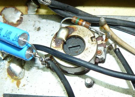
These images show the bias balance pot of a typical circuit. I have marked the 15kΩ grounding resistor (brown, green, orange, silver) mounted on the tapped adjust trimpot with a red arrow. In other amps it will look similar.
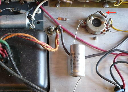
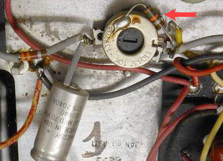
In some circuits the grounding resistor will have a different value, often 33kΩ (orange, orange, orange, silver), some Fender amplifiers have a trimpot without tap and two additional resistors instead. In some amplifiers the trimpot will be mounted on the back panel, labeled O.T. MATCHING, but the procedure will be the same, we only replace the grounding resistor.
This resistor, together with the trimpot resistance is a voltage divider network setting the bias voltage. We will remove the resistor and replace it with an adjustable resistance.
Since we want to be able to vary the bias voltage up and down, we want a resistance that is adjustable to less and more than the resistor we replaced. If the resistor was 15k we select a 10k resistor and a 10k trimpot, so we can adjust from 10k to 20k, and the old value is in the center of our adjustable range. If the circuit had a 33k resistor I suggest we use a 22k resistor and a 20k trimpot, so we can adjust from 22k to 42k. You get the idea, if your resistor is still another value?
We now install the new, smaller resistor value from the center lug, the wiper, of our new trimpot to ground, (a cermet multi-turn is the best but any trimpot will do) and connect one outer lug to where the old resistor was. That's it!
I have drawn a trimpot of the same type, but any type will do (except the ultra-cheap plastic ones). To prevent having to drill a new hole into the chassis of our vintage amplifier, we can mount the new trimpot, for example, on a small, angled piece of sheet metal mounted under the existing bias balance pot. Some trimpot types can be soldered directly on to the existing one.
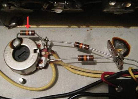
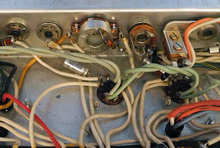
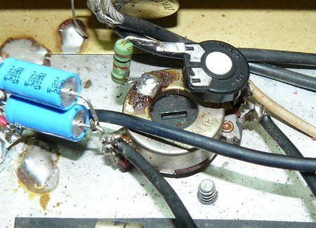
Here is an example, found somewhere on the web: the first picture shows the circuit prior to the modification (I just disapprove of the way the bias capacitor is installed, and there should be one instead of two). The second picture shows someone has added the bias adjust pot, soldered to the existing balance pot. My only objection is the type of the new pot, a cheap plastic one. Other than that this is well done!
The hum balance adjust
Likewise, the Hum Balance adjust pot some Fender amplifiers have on their back panel, is far superior to the virtual grounding of the filament supply via two 100Ω resistors, so disabling this adjustment feature and installing two fixed resistors instead is like disabling your car's air condition and opening the windows instead just because in the good old times, when everything was perfect, no one had air condition.
The adjustment
The adjustment of both balance pots is easy, and another advantage is that it can be done without a meter and without removing the chassis.
Bias Balance
Turn on the amplifier, go from standby to play and let it idle about half an hour. Now set all controls to zero (or rather, 1) and adjust the bias balance to minimal hum. The idle plate currents of the power tubes are now matched exactly.
Hum Balance
Similarly, with the amplifier running in play mode, plug a guitar cord from the NORMAL channel input to the VIBRATO channel input, turn up all volume and tone controls considerably or to maximum, and again adjust for minimal hum. The filament-induced hum is now minimized.
How to set the bias level is explained elsewhere, this is a highly opinionated issue. Personally, in most cases I start from about 25mA to 30mA idle current for 6L6GC tubes and 15mA to 20mA idle current for 6V6GT tubes, depending on the circuit, and adjust only if the amp sounds better with other settings.
Copyright BlueGlow © 2015