Why I won't let Gerald Weber service my vintage amps
Introduction
This is by no means meant to badmouth Gerald Weber or his work in general. This is also in no way intended to offend anyone. Gerald Weber has an impressive line of products including several books and videos, and at the very least deserves recognition for sharing information about tube amplifier repair and generally "keeping up the flame" when the technology was expected to go extinct. However, I recently found a video entitled Basic Tube Guitar Amplifier Servicing & Overhaul, apparently produced as advertisement for his services, and his books.
While I have not read the books, I wonder why he advertises his work with this video:
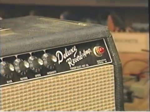
There are quite a few things I would never do when servicing an amplifier, let alone a valuable vintage amp such as the pre-CBS Fender Deluxe Reverb featured in the video. I disagree to the extent that I would never let Gerald Weber service my own amps.
Therefore, in this article, I will address some of them, and explain the reasons why. Moreover, in some cases, I will explain the right thing to do instead. Minor issues I disagree with will be ignored.
On the other hand the video shows a few things I think well done which I would do the same way, which I will not comment here.
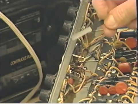
The corroded grounding bus
Weber begins by inspecting the amp chassis and says the grounding bus is corroded, He intends to pull out all controls and jacks to polish it.
 I will say, however, that it is completely irrelevant whether the grounding bus looks corroded.
It only needs to make good contact. A metal with corroded surface conducts electricity internally just as well as with a shiny surface. Since the ground connections are soldered on the board side, they will make good contact if the solder connections are good. The controls and jacks are connected by the mounting washers which eat into the surface, preventing corrosion at the contact point (to a degree).
I will say, however, that it is completely irrelevant whether the grounding bus looks corroded.
It only needs to make good contact. A metal with corroded surface conducts electricity internally just as well as with a shiny surface. Since the ground connections are soldered on the board side, they will make good contact if the solder connections are good. The controls and jacks are connected by the mounting washers which eat into the surface, preventing corrosion at the contact point (to a degree).
Of course it is nice to have a shiny brass plate there, but whether it is worth while removing it depends on whether it works, not what it looks like (and I have yet to see a badly corroded one in a Fender amp of this pristine condition. Even the one Weber shows looks perfectly OK to me including shiny solder joints, and he himself later says the nickel plated washers look nice and shiny which shows the work was not needed.)
A quick meter reading will tell whether the connections are good. There are good reasons not to remove the controls if it is not necessary. Not only is it often a waste of bench time, but removing the entire front controls and jacks will stress the single conductor wires. It is only to expect that one or more will break! So the repair work actually can cause faults that have to be repaired later on. Weber later even shows a broken tone control wire. Shame!
The filament polarity
Beginning minute 4:01 Weber states the power tube filament was wired incorrectly by Fender because the people who wired the amp did not pay attention. He stresses the filament supply wire going to pin 7 on one output tube should go also to pin 7 on the other output tube (and likewise for the other wire going to pins number 2). Later on he will rewire the filament supply (at minute 48:20). He states that way the output tubes will be hum-canceling.
I will say this is complete bunk.
- First, if one looks at the filament supply wires hooked up inside the tube, any tube, the wires are the same both sides and moreover connected completely random at the factory (except a few very special tubes such as the 36AM3B).
- Secondly, the tiny voltages on the cathode caused by the filament AC which may cause hum in the amplifier output will not have any measurable effect on the power tubes. This can be different in the input stage. The input of the amp is the most sensitive point in the amp, where each voltage will be amplified by a factor of thousands or more until it reaches the output. Microvolts may make a difference, and consequently some amps have a hum balance adjust pot here to balance that AC on the input stage filament for lowest hum (others have, a second best solution, two balance resistors to ground the filament DC wise, often 100 Ohms).
- Lastly, a slight mismatch in the output tubes' plate currents will cause much higher hum voltage levels than filaments can do!
Again, completely wasted bench time.
Replacing / installing the tubes
In my opinion, Weber handles the tubes and sockets pretty roughly, pulling and reinserting the tubes. The tube sockets need to function perfectly for the amp to work perfectly, so a bit more care is a good idea. It is a good idea to straighten the pins of new tubes to be inserted in the amp. The rough way Weber pulled the tubes can bend their pins which may have been perfectly straight in the first place!
New tubes sometimes come from the factory with bent pins, even new old stock ones, so I think it remarkable the only tube Weber installs without prior pin straightening is the new-out-of-the-carton one!
Tube sockets were not meant to plug / unplug tubes often. They were meant to easily install new tubes when the old ones were bad (instead of soldering the new parts in). It is a good idea to only plug / unplug tubes if it is necessary, to prolong the socket contact life – and avoid contact problems there which can cause arcing, sizzling, static noise and hiss.
The right way to pull tubes is rocking them gently in a very small circle while giving a slight pull. They will not come out immediately but without bending the pins or stressing the socket contact springs. The few seconds time invested here can save a lot of time later!
In any case I would not install new or reinstall the old tubes before all repair work is done. Moreover, the old tubes should be tested to see which ones need replacement! Later on, Weber finds it difficult to get at some solder joints because the tubes are in their places!
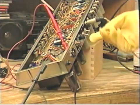
Placing the chassis on the bench
With the main filter capacitor replacement finished
 (I only wonder why Weber cuts the capacitors when he desolders the connection
later on) Weber turns the chassis around to work on the main circuit. At minute 37:10 he puts the chassis onto the bench so it rests on the tubes!
(I only wonder why Weber cuts the capacitors when he desolders the connection
later on) Weber turns the chassis around to work on the main circuit. At minute 37:10 he puts the chassis onto the bench so it rests on the tubes!
Ouch! Tubes are delicate items made of glass!
A better way is to put the chassis into a cradle made for this purpose, or at least support it with a book put under the chassis.
Damage by the repairman
After clipping out all the bypass capacitors on the main circuit board, only to desolder the leads later, at minute 43:31 Weber finds another damage he did himself accidentally, while clipping the capacitor leads.
My idea is, the repairman should not cause faults costing bench time the customer will pay in the end! I also wonder why no component values were checked, it would be nice to use the time to read the resistor values: carbon compositon resistors can drift greatly over time. The only resistor Weber apparently checks – at 1:08:00 – is the bias set resistor which is the only one you do not need to test usually, as it connects to an adjust pot, so any drift can usually be adjusted away.
At minute 1:17:00 he finds another resistor he accidentally disconnected while replacing the bypass caps.
Changing rectifier tubes
I wonder what Weber was thinking when he tests the voltages with different rectifier types (minute 1:11:21). Of course the actual voltages will depend on the rectifier type used!
However, the circuit was designed for a particular rectifier tube and should be brought up to work perfectly with the that type. Because Weber initially set the bias with a 5Y3 rectifier he has to reset the bias again after installing the correct type, GZ34. (Another thing is that some rectifiers such as the 5U4 draw more filament current than this power transformer was designed to deliver).
Inspecting and cleaning the input jacks
Beginning at 1:00:29 Weber inpects the input jacks and finds a faulty one.
 Weber uses a "burnishing tool" like a file to make the grounding switch work again.
While I am not sure what exact tool Weber uses – it looks like a broken nail file – I would take great care which tool to use here.
To prevent corrosion, the steel or brass jack contacts are nickel plated. Although nickel may eventually develop a slight surface oxidation that prevents good contact, it appears the problem here was more of a mechanical nature.
If we use a file to clean the contact points, the nickel plating will be shaved off. We now have a clean, shiny metal contact, but no longer a surface that prevents corrosion for an extended time period. In other words, the jack may work a few weeks just fine, but develop new problems in a short time!
I use cardboard or a stiff piece of paper to clean this type of contact, and I avoid anything abrasive. (I wonder why the output jack is not checked the same way, in this case the shorting jack protects the output transformer from being blown if somebody plays the amp without a load connected to the output.)
Installing a grounded three-prong AC cord
Weber 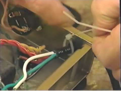 removes the old, two-prong power cord (it's not original anyway) using standard pliers to get out the strain relief. The new cord has three conductors instead of two, so, Weber states, it is a little difficult to get in because it is bigger in diameter.
Really? Fender always used pretty tough, thick cords that present no problem to the installation of a good, strong three-prong cord.
What follows I can only describe as tinkering: the new cord goes in no problem, but as a strain relief Weber installs a grommet and two tie wraps, one inside, the other outside the chassis.
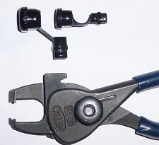
My opinion: A professional amp tech who regularly works on amps should have the right tools! There is a special tool dedicated to deal with the Heyco strain reliefs used in most amps' chassis: the Heyco pliers No 29. It is not even an expensive item! The correct way would be to get out the strain relief using the correct tool which will not leave dents in the strain relief , reuse it with the new cord which will go in without problems even if a good three-prong cord is used.
Besides, I would not trust the tie-wraps to really prevent the cord from moving when there is a strong pull. This is a matter of safety!!
(The reason to later bend the wires "out of the way" inside the chassis is, the rectifier tube socket is the hottest point in the entire amp. You would not want to risk the power cord insulation melting away here.
BTW Weber appears to leave the ground capacitor – often ill-named the death capacitor – in the amp. In amplifiers with a center-off ground switch I would usually do the same, but the matter needs to be addressed or discussed with the customer!)
Final test run
"Wailing away" after the final work should involve the test of all controls in the amp, not only the settings the repairman likes! One should check any possible setting of the controls even if you consider these wacky – you never know what settings the customer uses, and what additional fault one may find that was overlooked before!
Conclusion
Someone commented this video with the words "You are watching a master at work.". I hope I could make clear why I tend to disagree.
Copyright BlueGlow © 2014