Debunking Common Tube Amp Myths
Introduction
In no other technical area are people more easily willing to part with their money for their sonic ideal as in the realm of vacuum tube amplifiers. This is true both of tube-driven guitar amplifiers as well as ultra-expensive stereo gear. Though long expected to go extinct decades ago, in these two areas vacuum tube circuitry thrives today, but to the extent it lost its status of being the common, everyday technology of prosaic things such as home stereo and television, tube circuits began to be seen as a kind of mystic-laden technology of yesteryear.
Consequently, in no other technical area there are more myths, disinformation, and urban legends being spread. This is only partly due to the average layman's lack of understanding the physical nature and function of the electronic circuits concerned. It can also, on purpose, be used by vendors to justify their prices or to advertize average quality items as prime. In general, do not trust what salesmen tell you: their job is to sell, not to educate their customers.
The intent of this essay is to address a few of the most common myths, focusing on tube amplifiers used for electric guitar or bass. As an introduction, a few technical terms are explained. You can read this article in its entirety, or just the paragraphs linked to below. I have used easy to understand explanations, so no degree in electronic engineering is required.
Overview
Power ratingsImpedance mismatch
Headroom, overdrive, distortion, and overload
Why to replace tubes
Bias and classes of operation
The infamous 70% rule
Matched output tubes
About "Blackfacing" of Fender amps
Is point to point better than a PCB
Standby switches
Screen grid resistors
Tube gain and type swapping
The »cap job«
Power ratings
Electrical devices of any kind have a power or voltage rating, that is a maximum power or voltage value that will not destroy the device. Components such as resistors or capacitors often have a safe value printed on them. In other cases it is available on the manufacturers' data sheets. A given speaker rated 40W will safely operate if the power fed into it does not exceed 40W. These ratings indicate the power or voltage the device receives.
Devices that put out electrical power have a rated power output. With audio amplifiers these ratings are somewhat confusing as there is no specified method to measure the output power applied by all manufacturers. Often the power is given as RMS figure (Root Mean Square - a label that is frequently misused by audio manufacturers and technically without physical meaning). Different output waveforms of the same voltage size can differ greatly in power (hence "music power" is usually larger than the RMS rating given).
Electrical devices consume power from the power outlets or batteries, more than they put out on their outputs. E.g. for a Fender Deluxe Reverb a power consumption rating is given as 120 Watts while the maximum power output figure rates about 20 Watts which will be fed into the speaker terminals. Thus up to 100 Watts of power are transferred into heat, which is viewed as waste since heating is not the purpose of the amplifier. The rate of power output (eg going to the speaker) versus power consumption including wasted power is called the efficiency of a system. It is usually given as percentage and never exceeds 1 that is 100%.
Hence a speaker rated 100W can safely be operated in a 40W amplifier, but will not be fed more than 40W – it operates below its maximum design power (no big deal). A 40W speaker should not be hooked up to a 100W amplifier, as it is possible the amplifier will fry the speaker!
Impedance mismatch
There is a saying out there that usually has words like "a tube amp can work safely with a 100% impedance mismatch". This is just plain bad math. It leads to zero Ohms because any Ohms figure you name, minus 100%, is zero Ohms.
What is meant is that a tube amplifier with a specified output impedance of say, 8 Ohms, will safely work with a load of between 4 Ohms and 16 Ohms, and for many tube amplifiers this is true.
A better way to express acceptable mismatch would be to say: a tube amplifier will work safely with an impedance mismatched by a factor of no more than 2. That is, multiply the specified output impedance by 2 and you get the upper limit, divide it by 2 and you get the low limit.
Remember that a tube amplifier needs a load such as a speaker to push the output power into – if the power cannot get out of the output transformer, it may destroy it, instantly, not only after lengthy overload.
Headroom, overdrive, distortion, and overload
Quite a lot of confusion concerns the much-quoted, but rarely defined terms headroom, overdrive, distortion, and overload.
A signal transferring device such as an amplifier, signal processor or similar, can handle a certain input signal size depending on its design. If the input signal is larger, the device cannot process the signal the way it is intended to. This is called overdrive and usually not harmful to the device.
Since the input signal is too large to be processed by the device the way it was designed to, the output signal waveform is no longer the same shape as the input waveform. This is called distortion.
If the input signal is smaller than the device – say your amplifier – can handle, then the distance between the current signal size and the largest signal size below distortion begins, is called headroom (though this is not a technical term it will be recognized by electrical engineers). One sometimes reads about how a different preamp tube "increases headroom" of a particular amplifier. This is, of course, nonsense. All that is changed is the position of the volume control where distortion begins with the same input signal (to really increase headroom of an amplifier one needs to increase the maximum power output which involves a redesign of the circuit, in particular the voltages in the preamp and the power supply of the power output circuit must be increased).
If a device is fed more power than it can safely work with, damage may occur. This is called overload. In some cases, overdrive can cause output devices such as an amplifier to try putting out more power than it can safely handle. This is also overload and means the output devices eg tubes, transistors, or its power supply, or other parts are stressed beyond their intended range so again, damage can occur, either instantly or over a period of time, for example the power transformer or speaker voice coil runs too hot and fries.
Of course, in electric guitar systems, there are cases where overdrive and its consequence, distortion, are intentional. Whether a manufacturer puts the label Overdrive, Distortion, or non-technical names such as Fuzz on a product, is pretty arbitrary.
Why to replace tubes
In the 1960s and early 1970s there were not many reliable solid state guitar amplifiers available. It was common knowledge that a tube could go bad, so if the user identified the culprit, the tube type was noted carefully, the bad tube was removed and a new tube of the same type was installed. In most cases the circuit was working just fine after. Nobody worried about bias or matched tubes (though it is true that tubes manufactured before the 1980s usually were closer to the factory specs than many sold today. From some manufacturers such as Tung-Sol matched sets were available even before 1960).
Tubes can go bad in several ways, the most common are mechanical disintegration and wear.
The tubes' cathodes are heated by the filaments to give off electrons. To improve this so-called thermionic emission the cathodes are coated with materials which more easily emit electrons than the base cathode metal (which is often nickel). However these coatings, commonly containing Barium oxides, will deteriorate over time with use, and the emission gradually drops enough for the circuit to stop working properly. Thus we say the tube is worn and has to be replaced. The purpose of tube testers is to tell whether a particular tube is worn or good, apart from detecting other possible faults such as shorts.
Operating mechanically sensitive tubes in the same cabinet as a speaker which vibrates is a recipe to shorten the tubes' life. Hence in guitar amplifiers tubes, particularly power tubes, often do not last their electrical lifetime because the vibrations shake the mechanical construction and loosen the parts to a degree the tube develops faults of other kind, the most obvious being rattling and microphony. The latter means that the tube's electrical parameters, such as plate current, are sensitive to mechanical vibrations, similar to a microphone.
In the old days tubes were cheap (a June 1958 GE price list shows a 12AX7 for $2.55 and a 6V6GT for $2.15) so tube life was not of great concern. Today, with tube prices going into the hundreds for some tubes, this is different. To my knowledge, only some early Mesa Boogie Mark amplifiers used a shock-mount suspension for the chassis inside the cabinet (in some other amplifiers such as early Deluxe Reverbs, which have a "floating" baffle mounted only left and right so the center with the speaker can move, the chassis will not show much vibration.)
Addendum: Some tube dealers insist that when renewing the power tubes of an amplifier the customer should also replace the driver tube next to them. This is just sales lore. A quick calculation of the power applied to each tube in a typical guitar amp often shows the driver, also known as phase inverter tube, is the least stressed tube in the entire amp!
Bias and classes of operation
The simplest and most quoted way to understand bias is to compare the function of the circuit to the idling of a car engine. The reasons are different (the engine needs to idle even if no power is demanded, just to prevent it going out) but there is a similarity.
The reason an active element in an analog electronic circuit — be it a tube or a transistor — needs a bias current is the quality of signal transfer (digital circuits, whether logic or for switching, do not need bias).
A car engine is designed to be controlled by the gas pedal to deliver power from nothing to full power. The engine power follows the input signal, that is, the position of the gas pedal. The input signal, so to speak, goes from no foot pressure to fully down.
Similarly, an analog tube circuit is designed to transfer a signal, usually to amplify it, that is, the output signal should be larger either in voltage or power. Input signals, whether from a microphone, guitar pickup, or a preamplifier, are AC signals, which means the voltages available are alternatively positive and negative, so the average is zero.
To faithfully reproduce the input signal waveform, the idle current of a single tube or transistor is set at the center between zero and the design maximum current of the circuit. This way the current can go up the same amount as it can go down. This setting is called the bias point. At the output a capacitor or sometimes a transformer removes the DC part and we have an AC signal again.
Engineers term this principle of operation Class A. This in no way refers to the quality of the amplifier, it is just a technical term to designate the type of operation of a circuit. All preamp tubes in audio amplification work this way. Single ended audio power amps, i.e. amplifiers with only one power tube such as the Fender Champ, also work this way.
In a vacuum tube, the current is controlled by the voltage between (control) grid and cathode: the more negative the grid voltage, the lower the current.
The bias point is usually set by a resistor in the cathode connection to ground: the current through this resistor causes a voltage drop making the cathode more positive than ground, hence the grid, which is grounded, has the needed negative voltage in reference to the cathode. Thus the bias setting is determined by the resistor value and automatically set, to a degree independent of tolerances in tube specimens, making it "plug and play".
The downside is that the current through the resistor needs extra power and voltage. This is negligible in preamps, but in power amps up to a few Watts are wasted (converted to heat). Moreover, the amplifier always dissipates the full, rated power, regardless of whether there is a signal or not — in other words, e.g. tube life does not depend on whether the amplifier is used or not, only on the time it is powered on.
Hence, to improve efficiency, larger power amplifiers use a design referred to as "push-pull," where two or more tubes in pairs share the work, one side amplifying the positive half of the signal waveform, the other half is amplified by the other side. Push-pull operation as such still can be Class A, but ideally the idle current now could be set to zero, dropping the waste power to zero as long as there is no signal.
Radio transmitters work this way, though their power stage is usually single ended, as the output signal waveform is of no concern — this is dealt with by the antenna powered by the amp. This type of amplifier operation is termed Class B if the bias current is set to zero or Class C if the setting is even lower (the current cannot be lower than zero but the grid voltage can be more negative than the zero-current value).
Audio amplifiers however are designed to deliver the same waveform at their output they are fed into the input. If the idle current is zero, small input signals can easily vanish at the output (if the idle current setting is below zero) or deformed (this is called crossover distortion because it occurs when the signal amplification is taken from one tube over to the other).
So in audio amplification push-pull circuits, the idle current is always set to a value higher than zero to make sure that both halves of the power stage will deliver an output signal even when the input signal is very small.
Engineers call this type of operation Class AB, and this is the design operation of nearly all guitar amplifiers except single-ended ones, even if the manufacturer or the public claims it is "Class A". What is usually meant is the power tubes are biased by a cathode resistor (famous example is the VOX AC30 amplifier. Some manufacturers may be tempted to wave a sign saying Class A because the public may confuse it with First Class)
Another misconception is that a Class AB amplifier will work in Class A, if the signal is small enough for both halves amplifying the entire signal, until the volume rises. This is incorrect, a Class AB amplifier always operates in Class AB, regardless of whether the output devices carry the full waveform or not.
To further increase efficiency of the power amplifier, the bias voltage can be derived by an extra supply in the circuit instead of a cathode resistor, feeding a negative voltage to the power tube grids. Since no current is drawn, no power is wasted. The cathode resistor can be omitted. This is called fixed bias because the voltage setting is independent of the tubes plugged into the sockets. In these circuit designs, the power tube cathodes are usually connected to ground (the chassis metal) in the amp.
In many amplifiers this voltage setting can be adjusted with a screwdriver, thus yielding, somewhat confusingly, "adjustable, fixed bias".
Which bias setting is good for a particular circuit depends on a lot of parameters, such as the operating class of the amplifier, the design current swing of the plates, the intended load impedance range, the design maximum power output of the amplifier. The maximum design plate dissipation of the power tubes chosen for the circuit is only one among many, and not even the most important. In many cases the bias will be set in the center of the acceptable range so random pairs of output tubes will work safely with the intended load range, eg. to allow speakers from 4 Ohms to 16 Ohms.
Addendum: To read the bias currents of power tubes some people install a 1 Ohm 2W or 5W resistor from the power tube cathodes to ground. These resistors are not a bad idea — but let us calculate the necessary power rating for such a 1 Ohm resistor!
Power dissipation of a resistor is the square of the current times the resistor value. Even if we assume a very high idle current setting for each tube, say 70 Milliamperes, we get 0.0049 Watts of power. At full power output, with say 150 Milliamperes cathode current, the momentary power dissipated is 0.0225 Watts but this is a peak value, not constant or even average. So a 1/2 W resistor is therefore more than good enough. Installing resistors with more than a hundred times of the power rating necessary shows lack of understanding basic technology. I would much prefer to use a precision resistor instead of a high-power type with its typical tolerances of 5% or even 10%
(a 1 Ohm resistor will dissipate 1 Watt if the current is 1 Ampère which is one thousand Milliamperes).
The infamous 70% rule
The idea that in a push-pull power amp the power tubes should be set to idle at 70% of their maximum design plate dissipation is really an example of an urban legend running amok.
First, correctly applied, this is a rule of thumb that will give practical values for a wide range of circuits, but not in every case.
Secondly, as a rule of thumb, it indicates a safe limit to the bias setting, not a target value.
But a lot of folks have made a religion out of this rule and follow it regardless of all other parameters coming into the equation – I have even seen online calculators and figure tables!
This would be the same as claiming all cars using the same size tires must be run at the same speed, regardless of their engine or number of seats! We determine the operation of the car by its tire size. This is obviously absurd.
But let us assume for a moment it is true:
It means that if we have an amplifier A with lower plate voltage – say 360V – than amplifier B – which let us say has 450V – we must set the bias current in amp A higher than in amp B to get an idle plate dissipation that is 70% of the tubes' maximum value if both use the same type power tubes.
We totally ignore the operation class the amp was designed for, in this case the acceptable voltage swing to the power tubes' input grids and the cathode current swing. We further ignore there also is a maximum cathode current, so if the idle current is set too high, we limit the current signal size. Also we disregard the amount of power the amplifier's power supply circuit was designed to deliver.
Now, usually higher plate voltages go with higher output power of the amp, so we end up with the low power amp A idling at a higher percentage of its maximum power output than the higher powered amp B, thus reducing its maximum output power. This is obviously nonsense.
But let us look at some real figures given in the manufacturers' data sheets, in this case from General Electric from March 1959. The data refer to the 6L6GC power tube and the figures are the same as in Sylvania's Technical Manual, 13th edition, from 1968. Maximum design acceptable plate dissipation is given as 30 Watts.
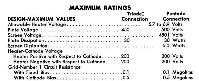
Let us begin with a Class A push-pull amp:
First we note the higher plate voltage goes with higher idle currents; the figures do not differ much, though.
In the first case we have 60 Milliamperes idle current (zero-signal plate current values listed are for two tubes!) at 250 Volts on the plate. Now 250 Volts times 0.06 Amperes yields 15 Watts idle dissipation, exactly 50% of the maximum allowable 30 Watts!
The second set of data, with 270 Volts on the plates and 67mA idle current calculates to 18.1 Watts idle plate dissipation, about 60% !
Remember this is Class A where 100% would be possible! We also note the idle dissipation is close to the maximum power output of the pair, which makes sense for Class A. The engineers designing the circuit determined the bias current by the current swing the circuit is intended to operate with!
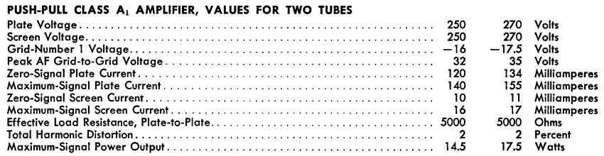
As we know, the average plate dissipation in Class A is highest with no signal, so let us consult Class AB1
operation (the index 1 means no grid current at all times).
Again we can see that higher plate voltages correspond with higher idle current settings, a direct contradiction to the 70%-is-the-target idea. We also see a larger difference between maximum signal current and idle current – which we expect in Class AB: that is the point.
In the first case we have 44mA idle current (per tube!) at 360 Volts on the plate, which yields 15.8 Watts idle dissipation, this is 53% of the maximum value !
With the second set of data, with 450 Volts and 58mA idle current, we calculate a whopping 26.1 Watts idle plate dissipation, this is 87% !
In this case we get the maximum output power these tubes are designed to deliver as a pair, but with this bias setting we can no longer assume that the amplifier will be tolerant of output impedance mismatches (see above). With the tubes idling at 87% of the maximum, we must take care the output impedance really matches the design value!
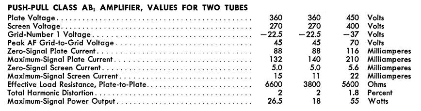
Let us now look at the data given for Class Class AB2 operation!
We note that although the plate voltages listed are lower than with the figures given for Class AB1, the idle currents listed are also lower! We further see the signal voltage range now includes up a to few Volts positive on the control grids for each tube. During these times the tube will draw some control grid current, not a problem for the tube, but we now need a driver i.e. phase inverter circuit capable of delivering that current, usually by DC coupling, not normally found in musical instrument amplifiers (the Ampeg SVT bass amplifier being a noteable exception).
Let us calculate the idle plate dissipation again!
In the first case we have 39mA idle current (per tube!) at 360 Volts on the plate which yields 14 Watts idle dissipation, for the 70% religion folks a shocking 47% !
With the second set of data we see the same plate voltage but different output load impedance and input signal voltage, and at 44mA idle current, we calculate 15.8 Watts idle plate dissipation, which equates to 53% of the maximum value.
Conclusion: the bias setting is not a particular, exact value derived by the tube type and the plate voltage at idle, but an acceptable range the limits of which depend on operation class of the circuit, the intended signal current swing, the intended maximum design output power, acceptable harmonic distortion figures, intended output load range and many other parameters.
With guitar amplifiers, the designers usually took into account that the player may plug in different speaker enclosures, the tubes may be replaced without a tech carefully reading the currents and setting a bias voltage, and considering other parameters. So in many cases, as a rule of thumb, the 70% rule will show the safe limit to bias current, but usually lead to tubes running hot. In particular an amplifier with lower plate voltages will be set too hot if biased at 70%, detrimental to tube life, the amplifier's power supply, and to other components because of the additional heat.
Matched output tubes
Until the 1980s few users of tube circuitry cared or even knew about power tube matching. Since the major manufacturers of tubes in the United States and Europe discontinued their production, tubes have been produced in countries such as China, Russia, and very few other places. Considering that tubes no longer were at the forefront of technology, many tubes of questionable quality were sold, as well as tubes no longer closely meeting the factory specs of the type, or tubes that are labeled one type but are actually another (Russian and Chinese 5881 being the most common examples).
Hence, to a degree it is indeed worth while making sure that in push-pull power amps tubes are matched. But what does this mean?
In order to get the best performance out of a push-pull power stage, both halves of the power section should operate the same way. What parameters should be matched?
In order to avoid hum and magnetic imbalance in the output transformer, the idle plate currents of the tubes must be close to each other. This means at the bias point of a particular amplifier, both tubes or pairs must draw similar currents, ideally the same.
Also, to make sure that both halves of the push-pull transfer a signal the same way, the transconductance of the tubes should be the same. This is the ratio of plate current change versus grid voltage change. The better this is matched, the lower the waveform correction required by the negative feedback loop will be.
A quick look at the data of any tube reveals that not only the plate current, but also the transconductance varies with the control grid voltage (otherwise the bias vary tremolo of amps like the Fender Princeton or Vibro Champ would not work at all!)
This means that a pair of power tubes matched for currents and transconductance in one amplifier may be unmatched in another, moreover, even in the same amp the tubes may be matched with one bias setting and unmatched with another. What is worse, the actual currents and other parameters of tubes drift over time, the most within the first hundred hours of use when new.
In other words, unless the vendor explicitly states which parameters of a "matched set" were measured under which conditions after at least 24 hours of burn-in, the label "matched set" is worthless, just another buzz word to pull more money out of the customer.
As a practical example, it would be perfectly good enough if a set of tubes matches transconductance within 10% or even 20% and the idle currents differ only a few Milliamperes (if the same measurements are taken another day, one will find different values anyway).
If you use a Fender amplifier also see the following paragraph.
About "Blackfacing" of Fender amps
In recent years it has become the fashion to "blackface" the so-called Silverface Fender amplifiers made between late 1967 and the mid 1980s. While some circuit changes introduced by the CBS corporation who now owned Fender were not for the better and a particular amp may benefit from returning to the earlier part values used, often also the Output Tubes Matching bias balance adjustment is ripped out and replaced with the earlier style bias setting adjustment.
I have never heard of anything more stupid: that was the one good idea the CBS engineers introduced, allowing the owner to use output tubes mismatched in plate current, or to rematch them for drift after years of use. It is a pity the bias setting option was dropped by CBS with that change.
But even so, it is a much easier, simpler and less invasive change to add a bias adjust pot to the existing balance setup and keep the balance, instead of replacing it with the earlier bias adjust: one only needs to replace the grounding resistor on that pot with another trimpot (the procedure is explained in detail here).
Likewise, the Hum Balance adjust pot some Fender amplifiers have on their back panel, is far superior to the virtual grounding of the filament supply via two 100Ω resistors, so disabling this adjustment feature and installing two fixed resistors instead is like disabling your car's air condition and opening the windows instead just because in the good old times, when everything was perfect, no one had air condition.
Today we regret the many pickup routings, additional holes, finish stripping etc. that in the 1970s were carelessly done to many vintage guitars of the classic era, but this kind of tinkering, to me, is of the same quality.
Is point to point better than a PCB
It can be a nightmare to service devices using printed circuit boards, in particular low-to-medium quality ones. A little bit too long with the soldering iron on the copper traces, and they come off, making every further repair messy. Sometimes also the holes the old parts are fed through are so narrow the new parts will not go in easily.
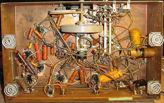 But similarly, some point-to-point wired circuits, in particular the ones made before the 1960s, can be a comparable nightmare, because the wiring makes up a rat's nest where individual components cannot be accessed since a lot of other wiring is in the way, and because of the way wires are soldered into the terminals of sockets, pots and switches after being fed through the holes and then bent around them before soldering. Removing these cleanly without damaging other parts, even after clipping the wires off, can drive the repairman nuts.
The exception is, of course, if the designers kept later repairs in mind and made all parts easily accessible, such as in the classic Fender amps that have all components on a two-dimensional eyelet board, or circuits arranging the parts as easily accessible on terminal strips.
If a circuit is well thought out and designed, PCB electronics can be every bit as good as the best point-to-point wiring design, possibly even better because of the shorter connections and lower stray capacitances.
Standby switches
Why some tube amplifiers are equipped with a standby switch is not entirely clear, likely by popular demand. Then there is the question of how to use it. But of course it is convenient to switch off the amp for short breaks or to change instruments with the tube filaments heated, so the amp can be switched on again instantly.
It is often claimed that applying the high plate voltage to the tubes before the filaments are hot may damage the tubes by the so-called cathode-stripping, that is, the high voltage accelerates ionized gas atoms in the tube towards the cathodes which, when cold, are not yet able to give off enough electrons. The purpose of the standby switch is thus explained to make it possible to heat the tube filaments before the high plate voltage is applied.
This is incorrect. With the (comparatively) low plate voltages of musical instrument amplifiers, rarely exceeding 500 Volts, cathode stripping does not apply. This can be different for large radio power transmitter tubes with many thousands of volts on their plates, and for tubes containing gas such as thyratrons and fluorescent lamps.
It is sometimes claimed, in amplifiers without standby switches the rectifier tube takes the place of the standby switch by providing a "soft power up," as the rectifier delays the high voltage feed. But if that would be the case, surely the rectifiers' cathodes would be subject to cathode-stripping! Whether directly or indirectly heated, they are of the same type, namely low-temperature oxide coated cathodes.
Many smaller tube amplifiers do not have a standby switch. Have you ever heard of these wearing tubes too fast?
It does not hurt heating the tubes up before the amp is fully switched on, but no use of the standby switch will cause any damage (unless you leave the amp powered, on standby, for longer periods such as days or weeks).
Too much filter capacitance, on the other hand, in particular of the first capacitor directly charged from the rectifier, may stress the rectifier cathodes because of the current rush during power on and each 50Hz or 60Hz cycle the capacitors are re-charged in operation, so it is recommended the maximum capacitance found in the data sheets is not exceeded. For a 5Y3GT rectifier for example GE listed a maximum of 20μF.
Screen grid resistors
Most Fender
 amplifiers using 6L6GC or 6V6GT output tubes have 470 Ohm 1W screen grid resistors. Amplifiers using EL34 or EL84 output tubes often have screen grid resistors of higher values and power ratings.
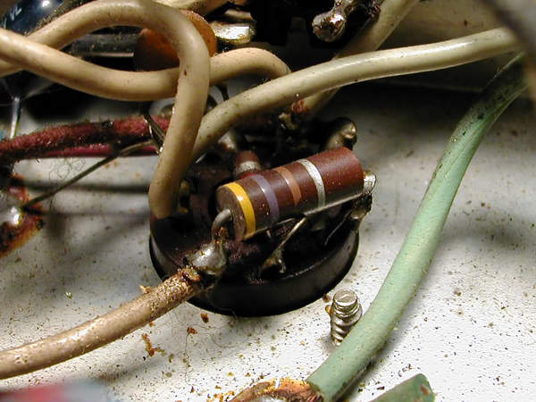
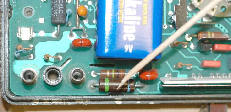
The purpose of the screen grid resistor is to limit the screen grid dissipation by limiting the current. Also, if a short occurs in the power tube, it is intentional the screen resistor is destroyed (would you rather replace a $1 screen resistor or much more expensive parts such as power transformer or a choke?). In many amplifiers these are fusible resistors which will fry by breaking in two thusly disconnecting instead of going up in flames like resistors of other types might do. The picture below shows the inside of a Fluke multimeter with the toothpick pointing to a fusible resistor.
Therefore, although it is often seen, it is controversial whether it is a good idea to install high-power resistors on the screens such as a 5W type, let alone wirewound ones which might go to internal red glow before they fail. Some people may prefer not to replace the screen resistor each time a tube develops a screen short, but I wonder why they would not prefer to use a more reliable brand of tubes instead. (The Fender circuit designers knew what they were doing when they specified 1W carbon composition resistors. The smaller amps, Champs and Princetons, have no screen resistors on the sockets, because a similar resistor is used in the power supply chain performing the same function. The larger amps use a choke in this place which has a very low DC resistance and will not limit the current to safe levels if there is a screen short in a power tube).
EL34 and EL84 tubes are very common power pentodes which means these tubes have three grids, the middle one being the screen and drawing electrons like the plate, as it is on a high positive voltage similar to the plate voltage.
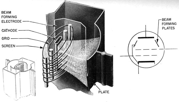
6V6 and 6L6 tubes and many others, such as the KT66, KT88, are beam power tetrodes which means they do not have a third grid, they have a "beam forming plate" performing a similar purpose as the third grid, the suppressor grid of pentodes. Moreover, the screen grid wires are, so to speak, in the shadow of the control grid as viewed from the cathode which emits the electrons. Thus, fewer electrons hit the screen grid and for a typical beam power tube the screen currents are much lower than for pentodes. Therefore pentodes need a screen resistor of higher resistance and higher power.
Another myth is that the screen voltage must be below the plate voltage for safe operation at all times. Nonsense! The power tube is an amplifying device so its plate voltage will vary. At full output its voltage swing may be hundreds of volts in some amplifiers, including from close to double the supply voltage to close to zero. Naturally the plate voltage will then be below screen voltage momentarily. What matters is the average value.
Tube gain and type swapping
Something to keep in mind is that just because the tube base and the pin out is the same for any given group of tubes does not mean one can swap types without risk.
Most fashionable are 12A??7 preamp type swaps, but also power tube swaps to and from 6V6GT to 6L6GC or even EL34 types, the latter was popular in the 1980s.
Are 12AU7 and 12AT7 and their European counterparts, ECC82 and ECC81, interchangeable with 12AX7 (the European equivalent is the ECC83) types? Is the only difference their gain factor? Will a circuit employing a 12AX7 tube with its gain factor μ of 100 have a gain of 100?
All this is popular nonsense, some of it dangerous.
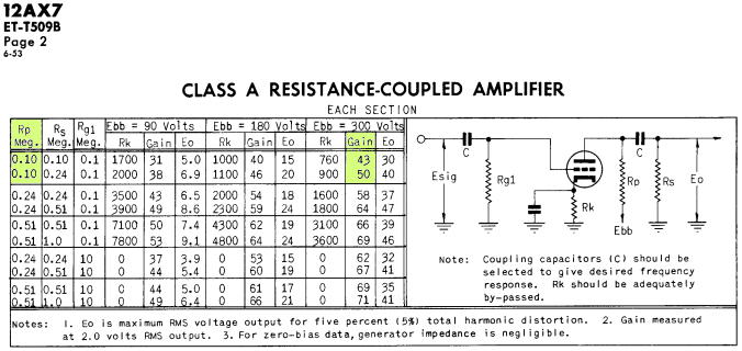
The gain factor of a tube is a purely theoretical value, calculated by its transconductance times its plate resistance. The transconductance of a 12AX7 is given as 1600 Micromhos, that is cathode current change in Microamperes per grid voltage change in Volts. Plate resistance is given as 62500Ω. Multiplication delivers a unitless figure of 100, the highest theoretical gain of a circuit using a 12AX7, provided the plate resistor is of infinite resistance. Real plate resistors are not, they best work at values of the same order of magnitude as the tube's plate resistance, most common value for a 12AX7 is 100kΩ. Thus real voltage gain of 12AX7 circuits is considerably less, usually around 50, as shown on this table (General Electric, June 1953)
Is the only difference of the 12A??7 types their gain factor? Let us see what the manufacturers say about the purpose of the types!
- 12AX7: this is listed as "resistance-coupled voltage amplifier, phase inverter, multivibrator". Other manufacturers list this as specifically intended for audio frequency use. The 7025 and 12AX7A (the European ECC83 is really a 12AX7A) are special low-noise versions.
- 12AY7 (no European equivalent): "designed primarily for use in low-level stages of high-gain audio-frequency amplifiers." Low-level means preamplifier. This is more or less the predecessor of the 12AX7.
- 12AT7 or ECC81: "grounded-grid radio frequency amplifier, or as oscillator/mixer for frequencies up to 300 megacycles." This tube was not even designed for audio application, although other manufacturers list driver or phase inverter application as acceptable in audio amps, since this tube has much higher current capability compared to 12AX7 types.
- 12AU7 or ECC82: "intended for service in radio and television receivers or audio amplifiers." Phase inverter, oscillator or multivibrator use is specifically mentioned. It was also often used as amplifiying tube in VTVM (vacuum tube volt meter) application.
As all of these have different transconductance, plugging one of these into a socket intended for another type will mess up its bias current. Moreover, for both 12AU7 and 12AT7 under "typical operation" plate currents of 10 Milliamperes are listed. Let us see what this would do to the typical 100kΩ plate resistor of most amplifiers. Dissipated power is resistor value times the square of the current. With 100000Ω times the square of 0.01 Ampere we get 10 Watts of power! No plate resistor of any preamp will survive this. In reality, most often the current will be less, so instead of instantly frying the resistor the additional current may limit its life, develop noise, drift etc.
Another thing to consider is that frequent swapping of tubes stresses the sockets beyond their intended use and limits their useful life, causing problems such as arcing, popping and static noise. Socket contact springs are designed for the best compromise of electrical conduction and spring pressure on tube pins. Best conductor material (other than silver) is copper, best spring material is steel. Often the socket contacts are made of a copper mixture with beryllium. Frequently moving/stressing these contacts will tire them and wear the tube socket. Of course one can try to retension the contact springs, but only so often before they give up.
As a general rule, your amplifier should run with the tubes it was designed for. If you do not like it, select a different amplifier or modify the circuit if different control settings do not help. There are acceptable tube swaps, though, if the tubes' parameters are similar enough. For example, the 5751 and the 12AY7 will work fine in 12AX7 slots because they were intended for the same purpose and have similar ratings.
If the power transformer can deliver the additional filament current, 6L6GC tubes can be used in 6V6GT slots if the amplifier is rebiased (but not vice versa!) That does not mean though that the amplifier will put out more power, because the output impedance is now mismatched and the power supply is still the same. The amplifier may however lose its special sweetness. In most cases the power supply will be insufficient to run larger output tubes, anyway.
The »cap job«
Some parts used in electronic circuits have a limited lifetime, sometimes whether used or not. For example, carbon composition resistors tend to drift over time and they can develop noise. Capacitors of some types may become electrically leaky and need to be tested (a well known example for this problem are the yellow Astron caps in 1950's Fender amps). Most importantly, electrolytic capacitors often go bad after decades, although some of them still work perfectly after 50 years.
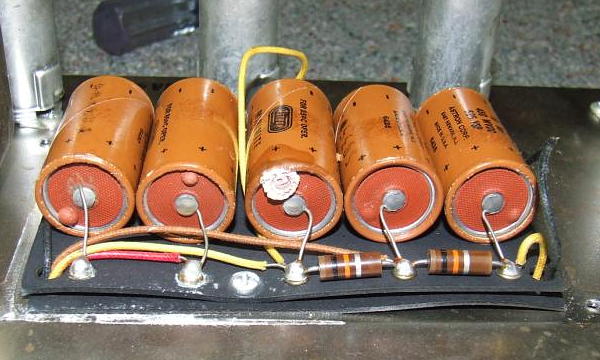
It is impossible to tell whether electrolytics will soon fail but in some cases there are signs indicating they probably will, such as shown in this picture, where the capacitors show typical bubbles or already ooze sulfuric acid.
Whether or not electrolytic capacitors should be replaced as part of regular maintenance depends on
- their age
- their position in the circuit
- whether they are still good
- the cost of replacing them including work
- whether they can do harm if they are good today but will fail tomorrow

When exposed to voltages above a few dozen Volts, electrolytic capacitors can explode just like a 4th of July firecracker, causing costly damage. The picture on the left shows the result (original capacitors of a late 60's Fender).
Therefore it is obvious that the high voltage types in a circuit should be replaced for safety reasons if they are over 30 years old, even if they are working just fine now. This refers to electrolytics operating with voltages of about 100 Volts and more, typically the so-called filter capacitors in the power supply such as the ones pictured above.
But you should be aware that even factory new ones, including the best brands, can fail just the same, as the picture on the right shows.

The bias circuits of power amplifiers usually also use an electrolytic capacitor or two. If these short out, the power tubes lose their bias voltage, draw excess current and can fry, and they can take the power transformer out as well. So it is wise if these are replaced for safety, too. This includes an electrolytic bypassing a power tube biasing cathode resistor, as there will be more than 10V and the capacitor operates next to a hot resistor, and if it fails the tube(s) may fry.
Many preamp tube stages use electrolytics as cathode resistor bypass capacitors. In operation, none of these see more than 10 Volts, most less than 2V. Even if they fail, they can do no damage, and with less than 10V no electrolytic explodes. So if these are good, I think it a waste of bench time to replace them, as you can tell in two minutes with an ESR meter whether they are good (typically I find 2 or 3 Ohms in Fender amps from the 1960s, new capacitors of the same rating have about 1 Ohm; the amp will work perfectly, like it was new, as long as the ESR value is below say 50 Ohms when it begins to affect the amplifier's performance. Even if it is higher, hooking them up to their rated voltage for an hour usually cures them).
Thus in most cases there is no need to replace the bypass caps! The exception are types known for frequent failure, such as the white plastic Mallorys typically found in 1970s Fenders.
If you really think that every electrolytic capacitor must be replaced after 20 years, why is it that so many solid state electronic gear from the 1970s to the mid 1990s, including stereos, radios, older guitar, bass and organ amps, let alone vintage effects pedals, to name just a few, is still around, working perfectly, although these items now are 20 to 40 years old?
Again, a nice comparison is with cars. Like it has been said many times before: if you drive a vintage muscle car, would you use the original tires? Of course not! But would you also replace the rubber handle of the gear shift lever, just because it is made of the same material?
Copyright BlueGlow © 2015